If a voltage source is applied directly to the input of an ideal amplifier with feedback, the input current will be:

Where vin is the input voltage, vout is the output voltage, and Zf is the feedback impedance. If the voltage gain of the amplifier is defined as:

And the input admittance is defined as:

Input admittance can be rewritten as:

For the Wien bridge, Zf is given by:


If Av is greater than 1, the input admittance is a negative resistance in parallel with an inductance. The inductance is:
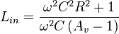
If a capacitor with the same value of C is placed in parallel with the input, the circuit has a natural resonance at:
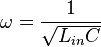
Substituting and solving for inductance yields:

If Av is chosen to be 3:
Lin = R2C
Substituting this value yields:

Or:

Similarly, the input resistance at the frequency above is:

For Av = 3:
Rin = − R
If a resistor is placed in parallel with the amplifier input, it will cancel some of the negative resistance. If the net resistance is negative, amplitude will grow until clipping occurs. Similarly, if the net resistance is positive, oscillation amplitude will decay. If a resistance is added in parallel with exactly the value of R, the net resistance will be infinite and the circuit can sustain stable oscillation at any amplitude allowed by the amplifier.
Notice that increasing the gain makes the net resistance more negative, which increases amplitude. If gain is reduced to exactly 3 when a suitable amplitude is reached, stable, low distortion oscillations will result. Amplitude stabilization circuits typically increase gain until a suitable output amplitude is reached. As long as R, C, and the amplifier are linear, distortion will be minimal.
An alternative approach, with particular reference to frequency stability and selectivity, will be found in Strauss (1970, p. 671) and Hamilton (2003, p. 449).
Where vin is the input voltage, vout is the output voltage, and Zf is the feedback impedance. If the voltage gain of the amplifier is defined as:
And the input admittance is defined as:
Input admittance can be rewritten as:
For the Wien bridge, Zf is given by:
If Av is greater than 1, the input admittance is a negative resistance in parallel with an inductance. The inductance is:
If a capacitor with the same value of C is placed in parallel with the input, the circuit has a natural resonance at:
Substituting and solving for inductance yields:
If Av is chosen to be 3:
Lin = R2C
Substituting this value yields:
Or:
Similarly, the input resistance at the frequency above is:
For Av = 3:
Rin = − R
If a resistor is placed in parallel with the amplifier input, it will cancel some of the negative resistance. If the net resistance is negative, amplitude will grow until clipping occurs. Similarly, if the net resistance is positive, oscillation amplitude will decay. If a resistance is added in parallel with exactly the value of R, the net resistance will be infinite and the circuit can sustain stable oscillation at any amplitude allowed by the amplifier.
Notice that increasing the gain makes the net resistance more negative, which increases amplitude. If gain is reduced to exactly 3 when a suitable amplitude is reached, stable, low distortion oscillations will result. Amplitude stabilization circuits typically increase gain until a suitable output amplitude is reached. As long as R, C, and the amplifier are linear, distortion will be minimal.
An alternative approach, with particular reference to frequency stability and selectivity, will be found in Strauss (1970, p. 671) and Hamilton (2003, p. 449).
No comments:
Post a Comment