The Clapp oscillator is one of several types of electronic oscillator constructed from a transistor (or vacuum tube) and a positive feedback network, using the combination of an inductance (L) with a capacitor (C) for frequency determination, thus also called LC oscillator.
It was published by James Kilton Clapp in 1948[1]. According to Vačkář[2], oscillators of this kind were independently developed by several inventors, and one developed by Gouriet had been in operation at the BBC since 1938.
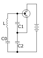 Referring to the notional circuit in the figure, the network comprises a single inductor and three capacitors. Capacitors C1 and C2 form a voltage divider that determines the amount of feedback voltage applied to the transistor input. The Clapp oscillator is a Colpitts oscillator that has an additional capacitor placed in series with the inductor. The oscillation frequency in hertz (cycles per second) for the circuit in the figure, which uses a field-effect transistor (FET), is

A Clapp circuit is often preferred over a Colpitts circuit for constructing a variable frequency oscillator (VFO). In a Colpitts VFO, the voltage divider contains the variable capacitor (either C1 or C2). This causes the feedback voltage to be variable as well, sometimes making the Colpitts circuit less likely to achieve oscillation over a portion of the desired frequency range. This problem is avoided in the Clapp circuit by using fixed capacitors in the voltage divider and a variable capacitor (C0) in series with the inductor.

It was published by James Kilton Clapp in 1948[1]. According to Vačkář[2], oscillators of this kind were independently developed by several inventors, and one developed by Gouriet had been in operation at the BBC since 1938.

Clapp Oscillator (direct-current biasing network not shown)
A Clapp circuit is often preferred over a Colpitts circuit for constructing a variable frequency oscillator (VFO). In a Colpitts VFO, the voltage divider contains the variable capacitor (either C1 or C2). This causes the feedback voltage to be variable as well, sometimes making the Colpitts circuit less likely to achieve oscillation over a portion of the desired frequency range. This problem is avoided in the Clapp circuit by using fixed capacitors in the voltage divider and a variable capacitor (C0) in series with the inductor.
No comments:
Post a Comment