The Armstrong oscillator[1] (also known as Meissner oscillator [2]) is named after its inventor, the electrical engineer Edwin Armstrong. It is sometimes called a tickler oscillator because the feedback needed to produce oscillations is provided using a tickler coil (T in the circuit diagram) via magnetic coupling between coil L and coil T. Assuming the coupling is weak, but sufficient to sustain oscillation, the frequency is determined primarily by the tank circuit (L and C in the illustration) and is approximately given by  . In a practical circuit, the actual oscillation frequency will be slightly different from the value provided by this formula because of stray capacitance and inductance, internal losses (resistance), and the loading of the tank circuit by the tickler coil.
This circuit is the basis of the regenerative receiver for amplitude modulated radio signals. In that application, an antenna is attached to an additional tickler coil, and the feedback is reduced, for example, by slightly increasing the distance between coils T and L, so the circuit is just short of oscillation. The result is a narrow-band radio-frequency filter and amplifier. The non-linear characteristic of the transistor or tube provides the demodulated audio signal.
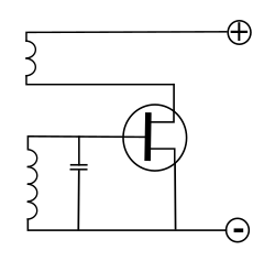 The circuit diagram shown is a modern implementation, using a field-effect transistor as the amplifying element. Armstrong's original design used a triode vacuum tube.
Note that in the Meissner variant, the LC resonant (tank) circuit is exchanged with the feedback coil, i.e. in the output path (Anode, Drain, Collector) of the amplifier, e.g. Grebennikov, Fig. 2.8[3]. Many publications, however, embrace both variants with either name; apparently the English speakers using Armstrong, and the German speakers Meißner.
. In a practical circuit, the actual oscillation frequency will be slightly different from the value provided by this formula because of stray capacitance and inductance, internal losses (resistance), and the loading of the tank circuit by the tickler coil.This circuit is the basis of the regenerative receiver for amplitude modulated radio signals. In that application, an antenna is attached to an additional tickler coil, and the feedback is reduced, for example, by slightly increasing the distance between coils T and L, so the circuit is just short of oscillation. The result is a narrow-band radio-frequency filter and amplifier. The non-linear characteristic of the transistor or tube provides the demodulated audio signal.

Armstrong oscillator schematic
Note that in the Meissner variant, the LC resonant (tank) circuit is exchanged with the feedback coil, i.e. in the output path (Anode, Drain, Collector) of the amplifier, e.g. Grebennikov, Fig. 2.8[3]. Many publications, however, embrace both variants with either name; apparently the English speakers using Armstrong, and the German speakers Meißner.
No comments:
Post a Comment